|
Application :-
|
Electro pneumatic is used for controlling movement of final control element such as Linear Cylinder, Diaphragm Control valve or Rotary actuator device which accept directly variable electronic signal & E/P positioner is a precision with the help of auxiliary high pressure supply accurately controls movement of final control element corresponding to set point. |
• |
Common unit for all type of actuators. |
• |
Simple calibration using three keys & LCD display |
• |
Auto start function with self adjustment of zero & span |
• |
Selectable freeiy programmable characteristic |
• |
Minium air consumption |
• |
Tight shut off function |
• |
Minium linkages to give error free feed back |
• |
No air consumption under balance condition hence saving of energy |
• |
Action field reversible |
• |
Digital output indicating precise position during operation |
• |
Unit can be modified for use with electrical actuator |
| |
|
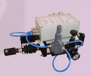
Construction :- |
Usually available in MS powder coated housing suitable for panel mounting with solenoid provided in separate weather proof housing & linear pot for field mounting. However optionally for field mounting with built in solenoid with die cased aluminium weather proof housing can be provided at extra cost. |
|
|
Operating System |
Positioner receives mainly three inputs such as : |
• 230 V a. c. 50 C/s, power supply |
• 4-20 MA-Input signal ( Control ) |
• Potentiomter - Output ( Feedback ) |
|
The microprocessor based instrument amplifier of the positioner receives variable input control signal & potentiometer output feedback signal. Microprocessor compares these values & depending upon vectorial difference decides & fires the corresponding relay which in turn triggers solenoid to admit & exhaust air from actuator. The system is based on modulation of signal & its time function. The microprocessor precisely calculates the time function & accurately positions. The movement of actuator standard instrument available with input control signal of 4-20 MA. However system can be modified for accepting other variable depending upon specific requirement. Similarly normal characteristic is linear, however optionally other characteristics such as equal percentage or square-root extraction is available |
• Simple installation & largely automatic commissioning.
• No effect of temperature or pressure variation.
• Maintenance free operation
• Calibration can be changed with display & key board. |
MODElS AVAILABLE |
• EP - Postioner-I
• EP - Postioner-II
• EP - Postioner - III |
|
OPTIONS AVAILABLE |
EPP-I / EPP-II / EPP-III, Panel / Field
4-20 mA / 0-1 V dc / 0-10 V dc / 0-20 mA dc Single / Double acting
Stroke of cylinder / Stroke of control valve or
900 rotary actuator |
| |
ADVANTAGES OVER CONVENTIONAL PNEUMATIC POSITIONER
1. I to P converter not required hence saving in cost
2. Reduced linkages hence maintenance free
3. "Can be remotely mounted
4. Calibration: is easy hence saving in time 5 Digital output of feedback position
6. Remote indication possible
7. Reduced air consumption hence saving of energy
|
APPLICATION
Linear cylinder
Rotary actuator
PN diaphragm control valve
|
| |
|
ORDERING INFOFMATION
• Type of positioner
• Type of mounting
• Type of input signal
• Type of actuator
• Stroke length
• Any optional extra feature
• Mounting: Pane! Mounted I Field mounted.
|
Note:
1. Product is processed & manufactured under technical guidance ofSMD Technologies - USA.
2. International Patent - Applied for,
3. Due to continuous research & development we reserve right for change of specification & upgradation |
| |
